Audiovox MMD10 User Manual
Browse online or download User Manual for Car speakers Audiovox MMD10. Audiovox MMD10 User Manual
- Page / 38
- Table of contents
- BOOKMARKS
- Owner/ Installation Manual 1
- Warnings 2
- A. Introduction 4
- B. Cautions and Warnings 4
- TOOLS REQUIRED: 6
- D. Installation and Powering 6
- VEHICLE PREPARATION: 8
- Figure 2 9
- MOUNTING THE MMD10 9
- Trim Ring Installation 10
- Figure 4 14
- Figure 5 14
- Figure 6 15
- Figure 7 16
- F. Loading and Playing a Disc 16
- SetTVStandard 24
- LoadFactorySetting 26
- ResetDefault 26
- 3. SUBTITLE 28
- MP3 file 34
- (Refer to Figure 8) 35
- O.Wireless FM Modulator 36
- Q. Troubleshooting: 37
- P. Specification 37
- 12 MONTH LIMITED WARRANTY 38
Summary of Contents
MMD10 10" LCD MONITOR & DVD PLAYEROwner/ Installation Manual
10Trim Ring InstallationThe Trim Ring Installation is accomplished using the four (4) 2.6X1 0mmscrews supplied. Please refer to the illustration below
117.Refer to the Owner/Install Manual for the MMD 10 to complete theinstallation.
12MMD101)Make the connections to the vehicle with the 5 pin wiring harness.2)Connect the 5 pin harness to the mating connector on the VideoMonitor.3)C
13CONNECTING THE DOME LIGHTSThe dome lights in the video monitor require three connections to thevehicle's wiring. There are two common types of
14Red / black - Lamp onBlack / red - Lamp commonViolet / brown - Lamp AutoTo 3 pinconnectoron MonitorToconstant+12vdcToconstant+12vdcFactory Door aja
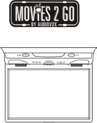
15E. Controls, Indicators, and Connectors1. Unit View (Refer to Figure 6)Figure 61) AV 2 In2) Headphone Jack3) FM Modulator Switch4) Auto/Off/On Dome
162. Remote Control View (Refer to Figure 7) 1)Power Button 2)Display Button 3)Angle Button 4)Subtitle Button 5)A-B Button 6)Slow Button 7)Paus
17POWERPLAYSLOWPAUSESTOPFORWARDREVERSEUP/DOWN/LEFT /RIGHTENTERNUMBERSRETURNMENUREPEATA-BDISPLAYANGLESUBTITLEAUDIOZOOMSETUPDVD/AV1/AV2EJECTPICTUREVOLUM
18H. SetupPress ‘SETUP’ to display the Main screen of the Setup Menu. Press‘SETUP’ again to exit the Setup Menu and the unit will resume it’s lastpl
19b).Select ‘Angle Mark’ using the UP/DOWN buttton, and then press theRIGHT button to enter the submenu. Choose Angle Mark on or offusing the UP/DO
2Note:This Product incorporates copyright protection technology that is pro-tected by method claims of certain patents and other intellectual prop-ert
20d). Select ‘Screen Saver’ using the UP/DOWN button, and then pressthe RIGHT button to enter the submenu. Choose Screen Saver on oroff using the UP/
21*On: The unit will return to the last position on the disc.*Off: The unit will not return to the last position on the disc.2) Select “Video Qual
22b).Select ‘Contrast’ by using the UP/DOWN button, then press ENTERyou can adjust the Contrast by pressing the LEFT/RIGHT button.
233).Select “Password” using the LEFT/RIGHT button, then press the Enterand press the RIGHT button to enter the submenu.Password Setup Page Screen Dis
244).Select ‘TV Type’ using the UP/DOWN button, and then press theRIGHT button to enter the submenu. Choose TV Type using the UP/DOWN button and t
25b. Select ‘Subtitle’ the using UP/DOWN button, then press RIGHT toenter the submenu. Select the desired subtitle language or SubtitleOff using the
26e. Select ‘Default’ using the UP/DOWN button, then press RIGHT to en-ter the submenu. Press ENTER to return all settings to the factory-setmode.NOTE
27I. MenuA DVD is divided into sections called titles and chapters. When youplay a DVD, a root menu of the disc will appear on the screen of yourTV or
282. ANGLEDuring playback of a disc, press ‘ANGLE’ to display the available anglesfor discs containing multi-angles*, with the current angle number (1
294. AUDIODuring playback press ‘AUDIO’ to select the audio language youdesire*, with the current Audio Channel Number (1) and the total num-ber of Au
3An LCD panel and/or video monitor may be installed in a motor vehicleand visible to the driver if the LCD panel or video monitor is used forvehicle i
306. A-B REPEATa. During playback press ‘A-B’ to set the Starting Point A.A-B Repeat Starting Point Screen Displayb. Press ‘A-B’ a second time to set
317. REPEATDuring playback each time ‘1/ALL REPEAT’ is pressed, the followingmodes will become available.Chapter: Repeat the current chapterTitle: Rep
32Total Elapsed: The current track playing and the total time that the CD has been playing.Total Remain: The curren
33L. Playing MP3 DiscsMP3 is a format for storing digital audio. An audio CD-quality song iscompressed into the MP3 format with very little loss of a
344. Use the ( NEXT ) button to move to the next song. Press the (PREVIOUS) button to move to the beginning of the previous song.USING
35M. Playing a Video Game (Refer to Figure 8)Change the source by pressing the DVD/AV1/AV2 button on theremote. The AV2 input jack is located on the
36FM Modulator FMFrequency Select SwitchO.Wireless FM ModulatorThe MMD10 is equipped with built-in wireless FM Modulator*, that al-lows you to listen
37 Q. Troubleshooting:No power at Video MonitorPower but no video orsoundPicture, but no soundREMEDY:-Verify +12 VDC on the Red wire at 2 pinPower Har
128-6429EAUDIOVOX ELECTRONICS CORP. (the Company) warrants to the original retailpurchaser of this product that should this product or any part thereo
4A. IntroductionThank you for selecting the MMD10. The main features include a10" Wide Screen (16:9 Aspect Ratio) Liquid Crystal Display (LCD)mo
55. DiscDo not use irregularly shaped discs such as heart or star-shapeddiscs as they may cause the unit to malfunction. Do not stick paper,tape or gl
6TOOLS REQUIRED:#2 Philips Screwdriver#1 Philips ScrewdriverUtility or Razor Knife or ShearsWire StrippersUpholstery hook tool (for removal of panels
7GENERAL INSTALLATION APPROACH:1)Decide upon system configuration and options that will be installed(i.e.: what components, VCP, Tuner, RF Modulator/e
8Notes :The MMD10 video system is only intended for an overhead,drop down installation. It is not intended for seat back or any othertype of mounting
9Figure 2NOTE: Two of the mounting holes are located under the domelight covers.If using the TRIM RING to mount the MMD10, please use the M3.5 x25mm
Related products and manuals for Car speakers Audiovox MMD10


 (58 pages)
(8 pages)
(12 pages)
(12 pages)
(21 pages)
(32 pages)
(32 pages)
(110 pages)
(16 pages)
(58 pages)
(8 pages)
(12 pages)
(12 pages)
(21 pages)
(32 pages)
(32 pages)
(110 pages)
(16 pages)
© 2020, manymanuals.com. All rights reserved. | 1.114 s |
 Manymanuals.com
 Manymanuals.de
 Manymanuals.fr
 Manymanuals.it
 Manymanuals.pl
 Manymanuals.cz
 Manymanuals.es
 Manymanuals-pt.com
Comments to this Manuals