Audiovox LCM5043NP User Manual
Browse online or download User Manual for Monitors Audiovox LCM5043NP. Audiovox LCM5043NP User Manual
- Page / 20
- Table of contents
- BOOKMARKS
- LCM5043NP & LCM5643NP 1
- WARNING: 2
- CAUTION: 2
- SYSTEM OVERVIEW 3
- OPTIONAL AUDIO CONNECTION 3
- MATERIALS LIST 4
- VEHICLE PREPARATION 5
- INSTALLATION 6
- Surface Mount 7
- Headrest Mounting: 8
- (Wiring Diagram) 11
- Monitor Removal: 12
- CONTROLS AND INDICATORS 13
- OPERATION 13
- MAINTENANCE 14
- REMOTE CONTROLLER 15
- MENU FUNCTION KEY: 16
- VIDEO SOURCE MODE KEY: 17
- VOLUME CONTROL KEY: 17
- SPECIFICATIONS 19
- 36 MONTH LIMITED WARRANTY 20
Summary of Contents
LCM5043NP & LCM5643NPRemote Controlled Color Display Monitorwith Headphone JackInstallation and Owner's ManualELECTRONICS CORP .®
11) Guide the cable through the sideopening of the Mounting Tray andplug it into the Monitor. Makesure the connector locks intoplace. Insert the Mon
ELECTRICAL CONNECTION (Wiring Diagram)10Video Source Input (1&2)Not UsedAV Output
The following procedure is to remove the Monitor from the MountingTray using the supplied Removal Tool. NOTE: Use care when per-forming this procedur
CONTROLS AND INDICATORSHeadphoneOPERATION1. Press power On/Off button to the On position. The LED powerindicator will light red.2. Press the Picture
MAINTENANCETo avoid electrical shock, do not open the enclosure. High voltageis present. No user serviceable parts inside the enclosure.Do not use any
REMOTE CONTROLLERNOTE: The Remote Controller supplied with this system is a stan-dard remote control, which is used to operate other systems. TheRem
15MENU FUNCTION KEY:The MENU Key is used to navigate between the Color, Brightness andTint adjustment modes. When the MENU Key is pressed an On Screen
16NOTE:For the LCM5643NP - Selecteither *NTSC or PAL, pressthe p or q Keys (CH/DISK/SET).VOLUME CONTROL KEY:To switch between Video Input Sources (AV1
17Replacement of Remote Controller Battery:1. Use a small coin to pry open battery holder from compartment.2. Remove old battery and put in a new one
18LCM5043NP:LCD Panel Size (Diagonal) ... 5"LCD Panel Format ... 9
1EXPLANATION OF GRAPHIC SYMBOLSWARNING:TO PREVENT FIRE OR ELECTRIC SHOCK HAZARD, DO NOT EXPOSETHIS PRODUCT TO RAIN OR MOISTURE.CAUTION:1. This product
© 2002 Audiovox Electronics Corp., Hauppauge, NY 128-6323AUDIOVOX ELECTRONICS CORP. (the Company) warrants to the original retail purchaserof this pr
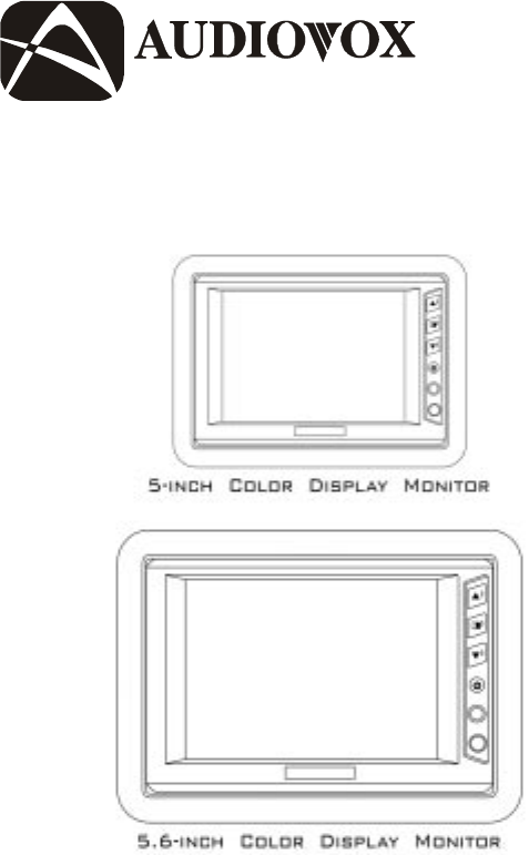
2SYSTEM OVERVIEWThe LCM5043NP is comprised of a 5" Thin Film Transistor (TFT) Liq-uid Crystal Display ( LCD) Monitor. The LCM5643NP is comprise
MATERIALS LIST1. System Monitor (LCM5043NP=136C2187) or (LCM5643NP=136C2186) (1pc.)2. Remote Control Unit (136B2156) with Lithium Battery, 3V,CR 2025
VEHICLE PREPARATION1) Decide on the system configuration and the options that will be in-stalled (i.e. what components, VCP, DVD, TV Tuner, Video Gam
510) After verifying the proper operation of the system, proceed to mounteach component.11) The mounting method, and the location will vary from vehic
63) Adjust viewing angle of monitor by tightening the fastener at theside.4) When the system components are mounted, test the system toverify that it
71) Remove the headrest from thevehicle for easiest installation.2) Lay headrest on a flat surface.3) Center trim collar on headrestas shown.NOTE: Dep
9) Using your fingers, tear the foamout of the headrest leaving a re-cess where the shell will be in-serted.NOTE: At this point you will need toinst
Related products and manuals for Monitors Audiovox LCM5043NP
 (16 pages)
(8 pages)
(11 pages)
(16 pages)
(5 pages)
(11 pages)
(8 pages)
(8 pages)
(36 pages)
(16 pages)
(7 pages)
(16 pages)
(8 pages)
(16 pages)
(8 pages)
(11 pages)
(16 pages)
(5 pages)
(11 pages)
(8 pages)
(8 pages)
(36 pages)
(16 pages)
(7 pages)
(16 pages)
(8 pages)
 (8 pages)
© 2020, manymanuals.com. All rights reserved. | 1.925 s |
 Manymanuals.com
 Manymanuals.de
 Manymanuals.fr
 Manymanuals.it
 Manymanuals.pl
 Manymanuals.cz
 Manymanuals.es
 Manymanuals-pt.com
Comments to this Manuals